EMC testing is essential to get a certification of Electromagnetic Emission and Immunity test before launching the product in the market. However, actual EMC tests are pretty expensive. Before going for the actual EMC test, the product should test in EMC pre-compliance test Lab. Pre-compliance testing will mimic all tests performed at EMI/EMC test labs to ensure the device will pass the EMI/EMC compliance test. Compliance test labs are very costly and difficult to pass; the pre-compliance testing cost is cheaper than the actual cost of EMI/EMC compliance test labs and will give approximately the same result.

图1预遵守框图
This article covers how to perform a pre-compliance test focusing on cheap or easy to set up tests to build confidence for actual EMI/EMC tests.
如前所述的文章中所讨论的,EMI / EMC是用于测量设备产生的电磁干扰的排放测试。EMI测试或电磁干扰测试限制取决于国家法规定义的标准。这也取决于产品或设备的应用。例如,医疗产品的EMI / EMC测试是严格的,因为医疗设备需要在任何条件下准确。如果医疗设备生成任何发射,那么它会影响其导致错误读数的其他医疗设备。
Types of EMI pre-compliance tests
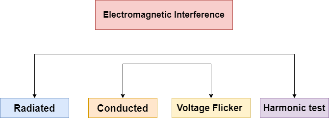
图2 EMI测试
The most common test which performs on almost every device is given in the block diagram. The reason for EMI test failure could be PCB design, shielding, components, antennas. These all lead to cause radiated and conducted emissions. That’s why most failures in the EMI test occur in Radiated and conducted emissions. Below some method is discussed to set up and measure radiated and conducted emission pre-compliance tests at the DIY lab.
辐射排放试验
两种方法可以测量辐射发射:远场方法和近场方法。在知道如何测量这些领域的辐射发射之前,让我们了解近场和远场测量之间的差异。
When oscillating electricity passes through a conductor, it induces a magnetic field. The induced magnetic field also creates an electrified field, as shown below. The H field represents the magnetic field, and the E field represents an electric field.

Fig. 3 E field (electric field) and H field
The device or equipment under test will produce both E field and H field. The electric field has a high impedance at the near of product, and the magnetic field has a low impedance called a near field. At a certain distance, the electric field and magnetic field combine at the same impedance, which is a far-field. The meeting distance of the E field and H field depends upon the frequency of waves.

图4近场和远场
近场辐射排放试验
A measurement probe is used near the circuit to measure the E field waves and H field waves. This is the cheapest measurement technique designers use to get an idea of troubleshooting in EMI tests on their products. The near-field test is not as accurate as a far-field test, but it gives an idea of EMI induced in the product during the pre-compliance test.
您需要一个频谱分析仪和测量探头来测量近场测试。市场上有一些昂贵的频谱分析仪,但“口袋RF探险家”或USB频谱分析仪加密狗可以在某些情况下工作。

图5频谱分析仪
There are various types of near-field probes available in the market, or you can make your own. The image below is of electric field probes; there are two probes, one probe has a pointed tip, and another one has a round tip. The rounded tip covers a wider area to measure the electric field in a circuit. Once the area is found where the electric field is generated, the small pointed tip probe will find the specific area of the electric field. These probes are not sensitive to orientation so that measurements can be taken in any direction.
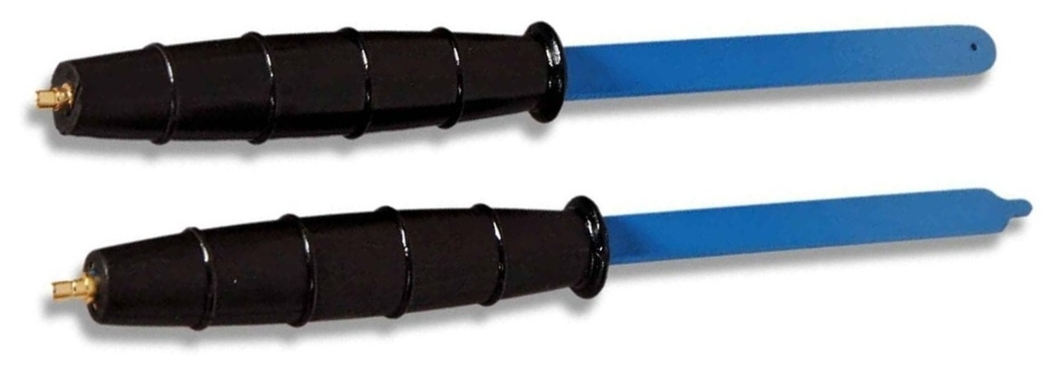
Fig. 6 Electric field probe
The magnetic field probes have a loop to measure the magnetic field. There are two probes in the image below: one has a small diameter ring, and the other has a large diameter ring. The large diameter ring measures the magnetic field in the wider area. After finding the magnetic field area, the smaller diameter probe can be used to find a specific area where electromagnetic fields are produced. These probes are very sensitive to orientation, so keep in mind that the readings will be taken at the same orientation, and the probe ring parallel to the circuit will give a much better result.
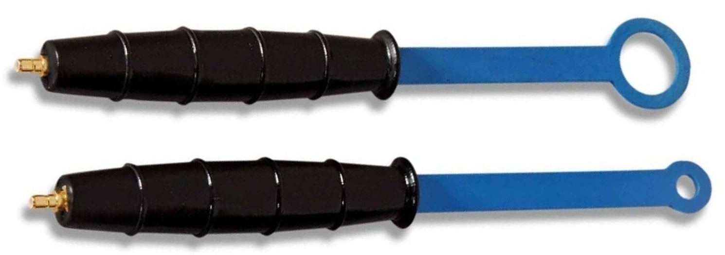
图7 Magnetic field probes
该设置需要一个RF放大器来放大来自探头的信号以进入频谱分析仪。标准探头带有放大器,但您可以在线购买RF放大器PCB进行DIY Probs。

图8 RF放大器
- DIY near H field probe
DIY probe can be made at a lower price than an actual probe in the market. Just buy a semi-rigid cable and follow the diagram given below. As in the diagram, make a loop of wire and solder its inner wire with an outer shield, and then solder it to make a loop as shown below.
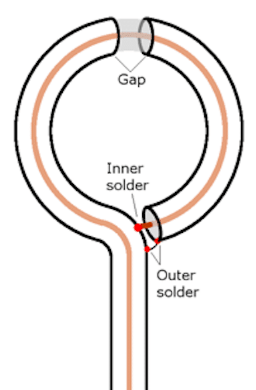
Fig. 9 Inner diagram on H field probe
After making this loop, cut the outer shield to create a gap between the loop, as shown in the image below.
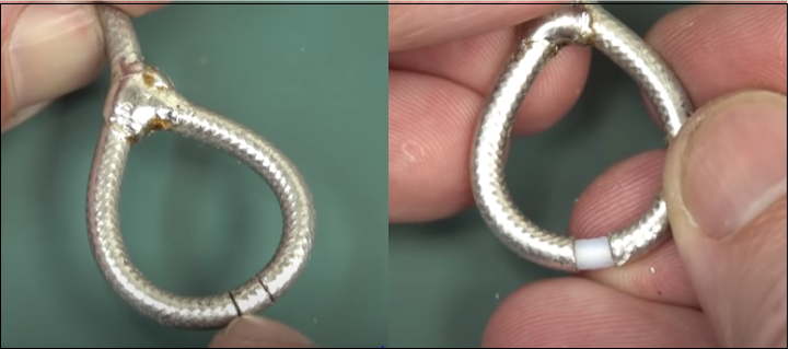
图10在H场探针中切割
Now dip it into an insulating paint or use some spray paint to get an insulating layer so this will not touch the open area in the circuit. Use a ferrite clamp to avoid external noise, as shown in the image.
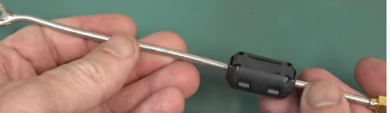
Fig. 11.1 DIY H field probe
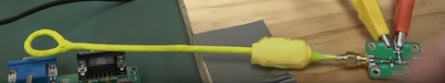
Fig. 11.2 DIY H field probe
远场辐射排放试验
Near-field measurement can only provide an idea of troubleshooting, but it cannot accurately read the emission. That’s why EMI/EMC test labs use far-field radiated emission tests. This is expensive and a little hard to set up. So it is not easy to set it up in DIY pre-compliance labs, but some EMC pre-compliance labs provide this setup. The far-field test can be performed in two types of areas.
- Open area test site (OTAs)
- Semi Anechoic Chamber (SAC)
- Open Area Site (OTAs)
在开放区域测试中,设置位于开放区域,其中最小的RF反射物体接近该区域。地面应该是反射和平坦的,所以天线可以直接从EUT(被测设备)和地面的反射来获得测量。
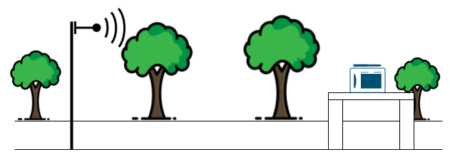
Fig. 12 Open area site
The minimum distance between EUT and the antenna should be 3 meters. If the distance is reduced to less than 3 meters, it will be considered near field measurement, which will be less accurate. To get accurate readings at 30Mhz, one wavelength is 10m, and at 100Mhz, one wavelength is 3m.
- Semi-Anechoic Chamber (SAC)
The semi-Anechoic chamber is made up of metal walls with RF absorbing material. RF Absorbing material absorbs RF signal produced by EUT. The size of the chamber depends upon which standard is applied to the product. The distance between antenna and EUT is generally 3m,5m, and 10m.

Fig. 13 Semi-Anechoic Chamber
- Spectrum analyzer/EMI receiver
As discussed in the near field test, every Lab needs a spectrum analyzer to measure the RF signals accurately. Ensure the spectrum analyzer can cover all frequency ranges that need to be investigated for EUT (e.g., 30Mhz to 5Ghz). Most Spectrum analyzers can measure “peak”, “Average,” and “quasi-peak”, Which helps in measurement.

Fig. 14 Spectrum analyzer
- Antenna
The antenna is the most important component of far-field measurement. The lower frequency measurement will increase the antenna size and cost, the Higher frequency measurement will reduce the antenna size and cost. The antenna must be calibrated to get the exact antenna factors needed for accurate field strength measurement. The maximum signal receives at a particular height so the antenna can move from 4 meters to 6 meters high to get the maximum EMI signal. the cheapest antenna will not able to measure low frequency. The image shown below is the PCB-based antenna to measure frequency from 0.6GHz to 10 GHz.

Fig. 15 Far-field measurement antenna for 0.6 to 10GHz
- Turnable table
在远场测量中,燕麦或囊需要可转动台,因为EUT器件的发射通常是定向的。该表应由木材或任何不会影响测量的材料制成。可转弯桌应以360度旋转旋转,以便在EUT的每个方向上进行测量。

图16带桌子
- TEM cell
这是测试辐射发射测试的另一种选择。TEM细胞代表横向电磁试验。TEM细胞由隔膜组成,中间的导电平面,与50欧姆负载连接。TEM电池捕获越小,较高的频率和较大的TEM电池将捕获较低的频率。可以根据频率使用适当的尺寸来购买或制造它。

图。17 TEM CELL
Conducted emission test
由于该测试所需的设备和设置要小得多,所进行的排放测试不和谐。您只需要一个频谱分析仪和LISN设备,用于发射预符合性测试。上面已经讨论过辐射发射不同的频谱分析仪选项。现在让我们了解Lisn设备的疗程是什么?
LISN stands for Line impedance stabilization network, this device is used for a Conducted emission test. The device will be connected between supply and EUT. It will help to measure the RF noise generated by EUT in supply. The RF noise measured by the LISN device can be measured using a spectrum analyzer.

Fig.18 LISN
EMI/EMC Limits
EMI / EMC限制取决于EMI的监管standards of the country. In the U.S., the interference is regulated by FCC (Federal Communications Commission). The FCC categorizes the devices in Class A and Class B. A Class A device is for industrial use, and the device intended for residential use is under Class B. The table below shows the Limits according to FCC for Class A and Class B devices.

图19 FCC标准限制
In Europe, the interference is regulated by CISPR. This is also categorized device in two categories. The categories are the same as FCC. Class A is for industrial devices, and Class B devices for residential. The limits for these devices according to CISPR are given below.
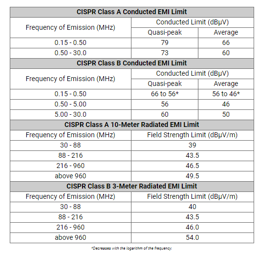
Fig. 20 CISPR standards limits
You may also like:


提起:188app彩票 ,188abc金博宝
Questions related to this article?
Ask and discuss onElectro-tech-online.com.和Edaboard.com论坛。
告诉我们你的想法!!
You must belogged in发表评论。